Design, Design, More Design
Part One - Modeling until it hurt...
This is the first time I have approached a project in this way. Normally I build things into commercially available enclosure parts, but you know, I am tired of being constrained to "industrial" looks and fixed sizes. And, I have an excellent 3D printer. I also have friends who work at companies that can grant me access to all their lovely 3D CAD software.
To ensure I can fit everything in a very compact space there is no other way except to design and fabricate by oneself- I decided to do everything from scratch, and the first item to start with, was the ASRock motherboard. I painstakingly measured every detail of it (none of my friends have 3D scanners), so it was down to doing it manually. Fortunately, for most of the components on that board, there are 3D models (STL files) available for free on the manufacturer's websites and also on the supply chain's websites (Digikey, Mouser, etc)
February 2026
Progressively, the model of the ASRock mainboard took shape...
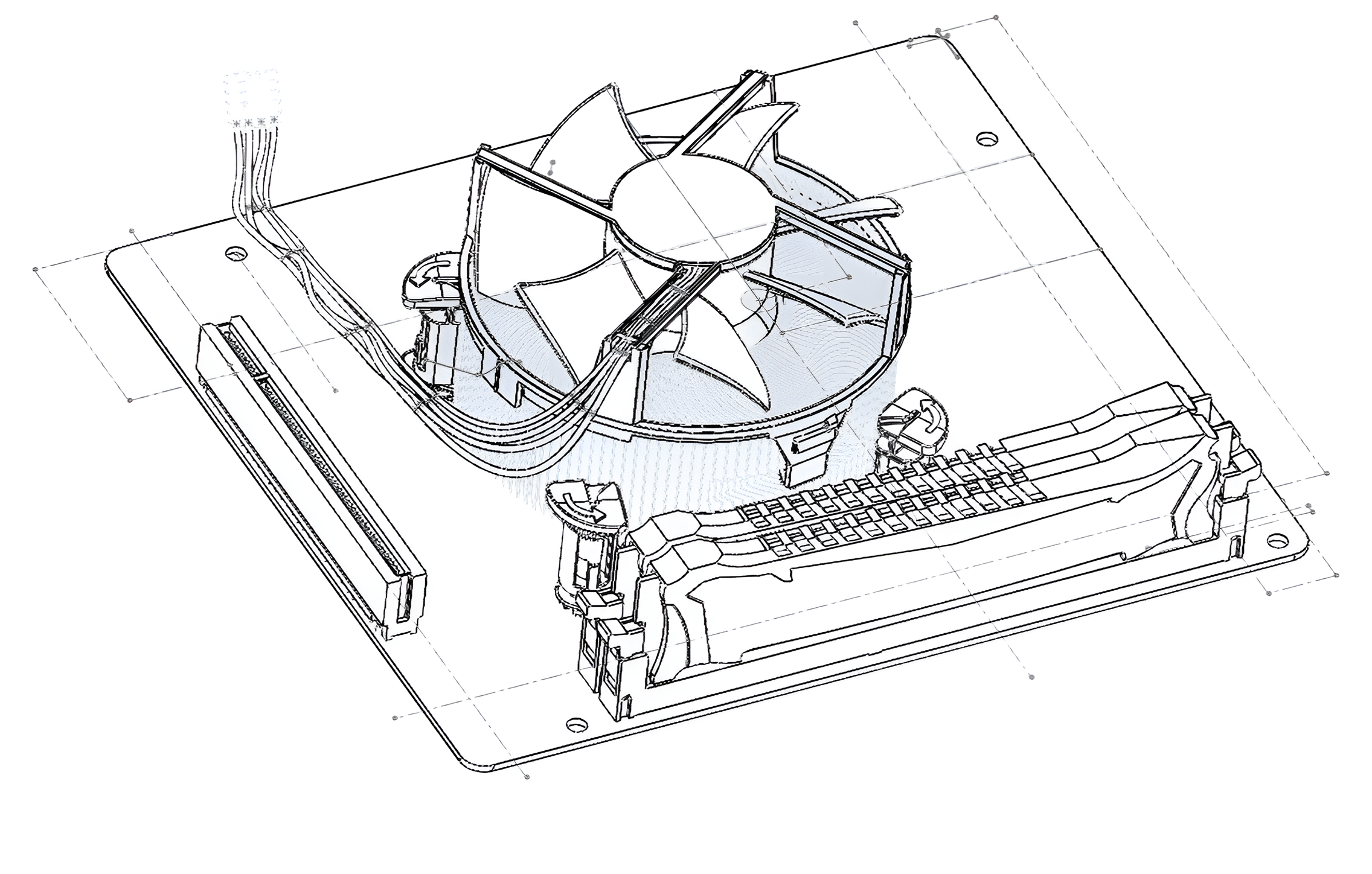
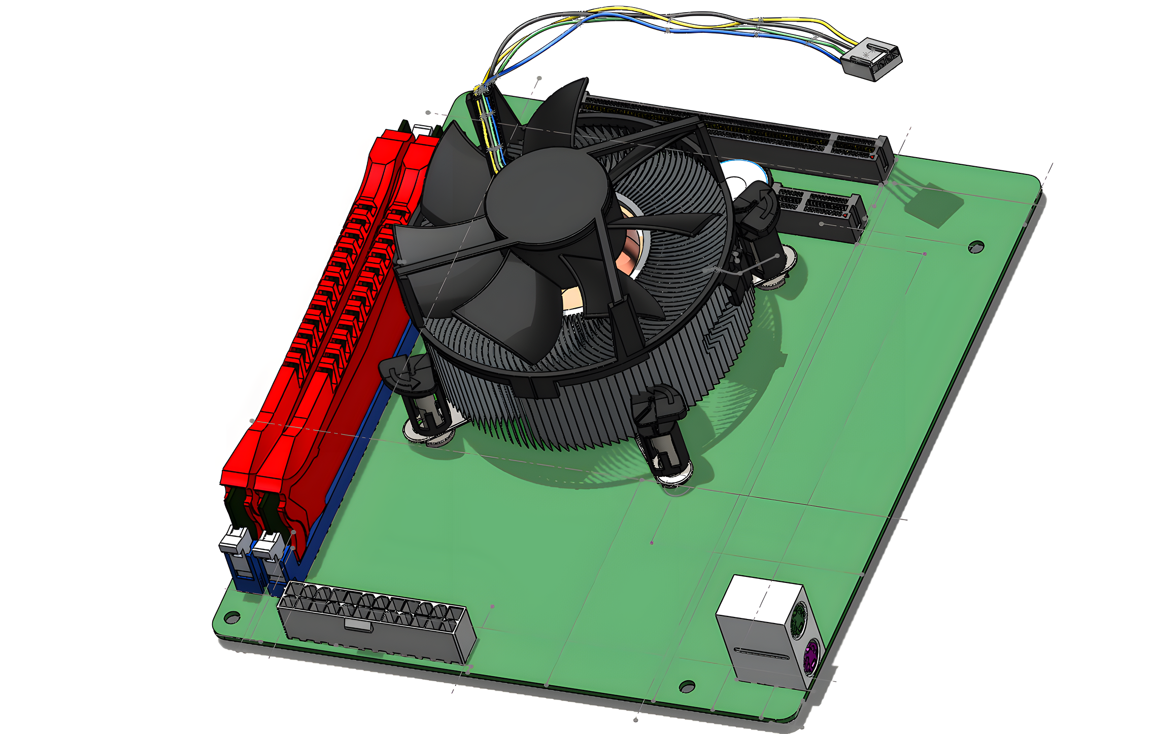
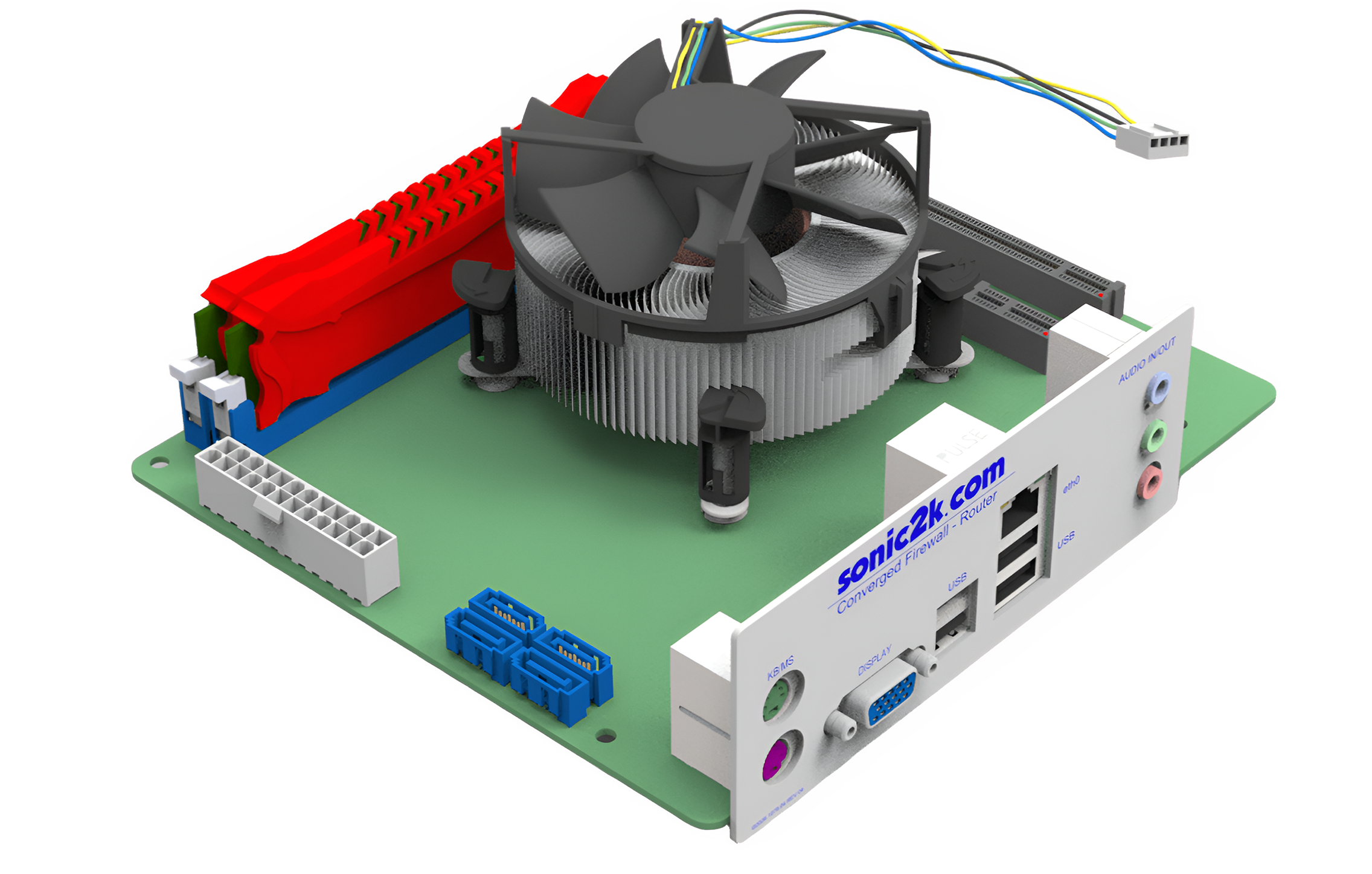
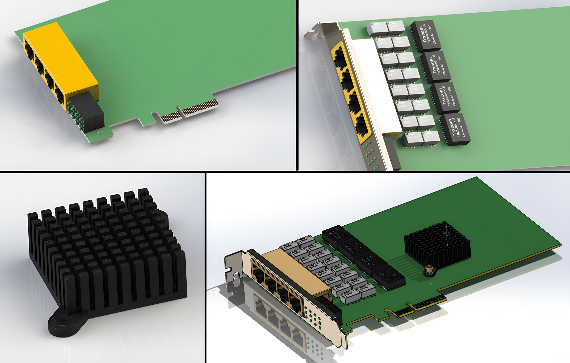
While the motherboard model was being worked on, I began to work on modeling that nice Riverbed Ethernet adapter as well...
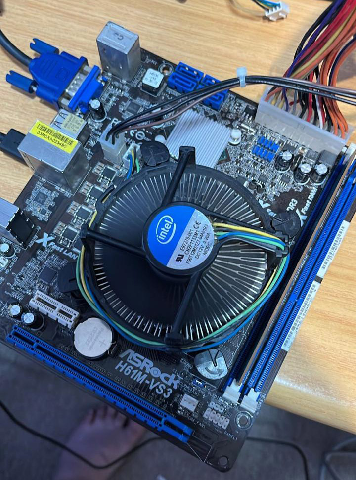
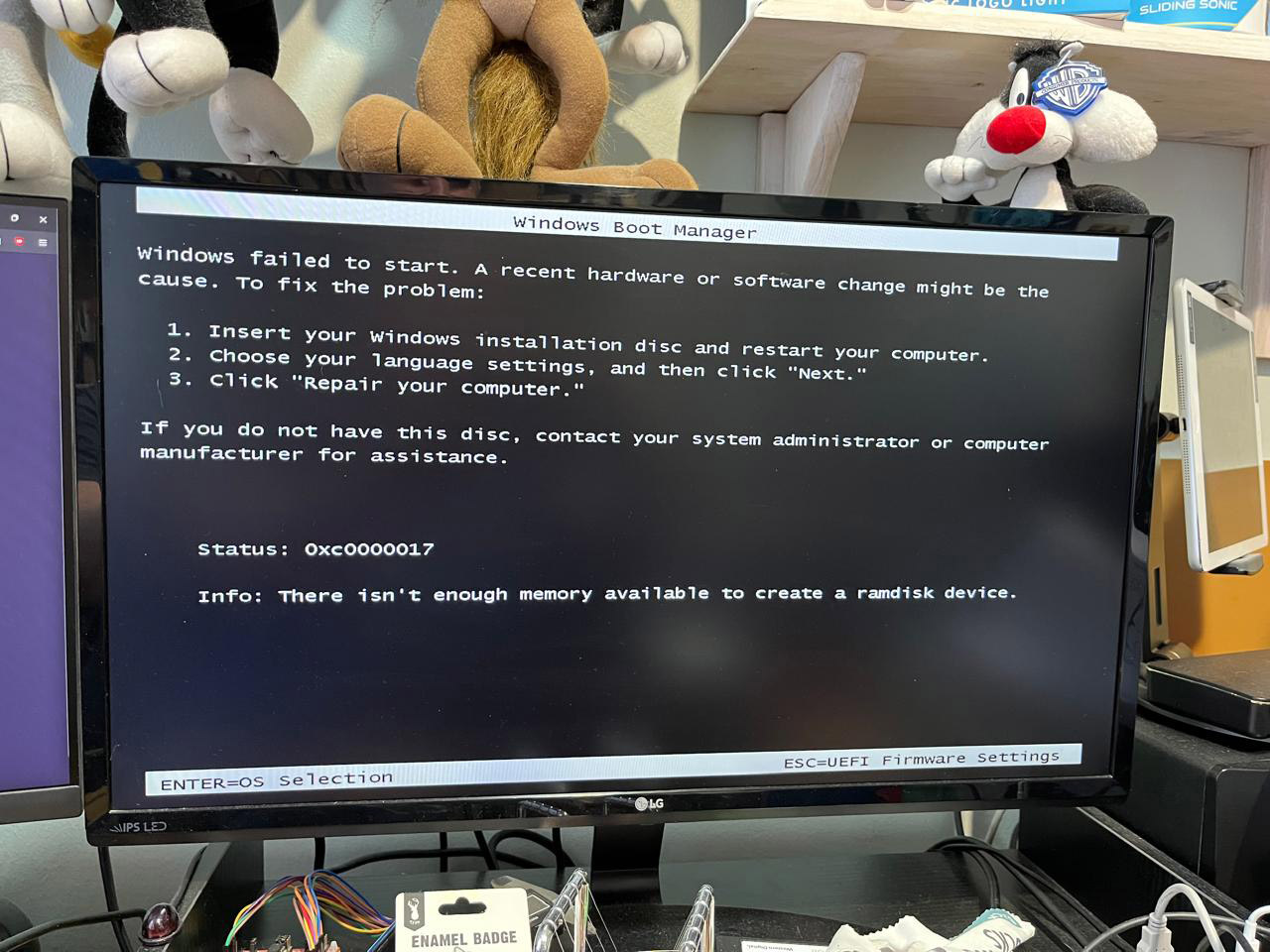
The motherboard was also tested during this time...
The "failed to start" screen was because I used a SSD with an existing image and yes 2GB is not enough RAM to run Windows 11
March 2026
I managed to get the power supply shipped from my friend.
It was immediately stripped down for examination. It did clean up nice later though!
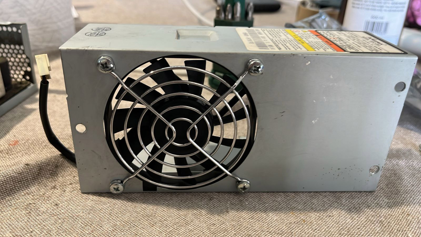
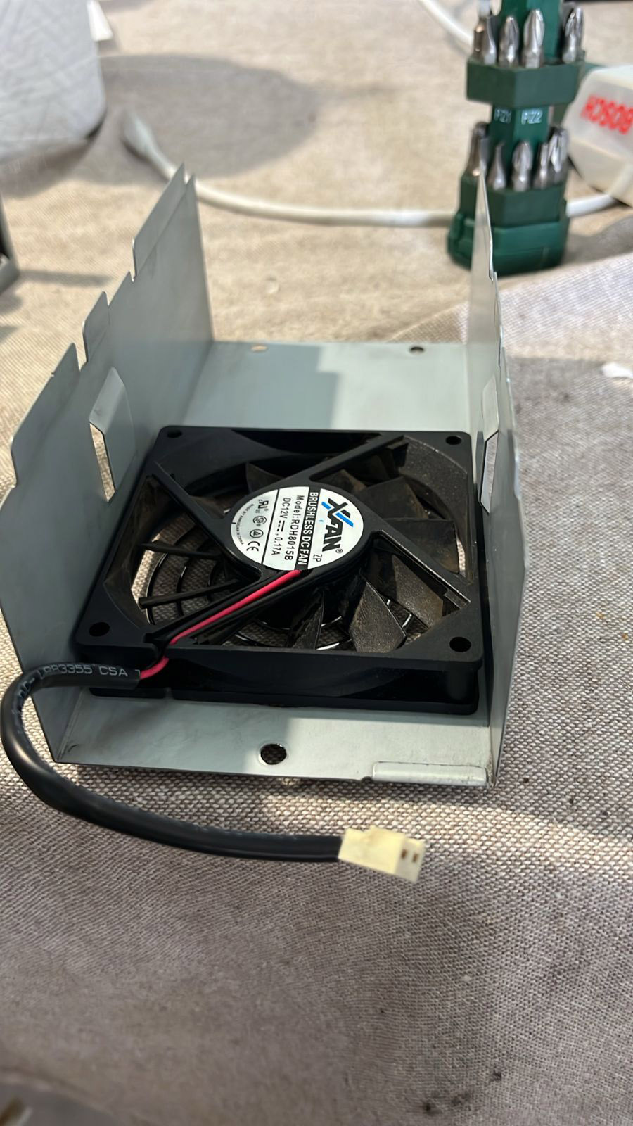
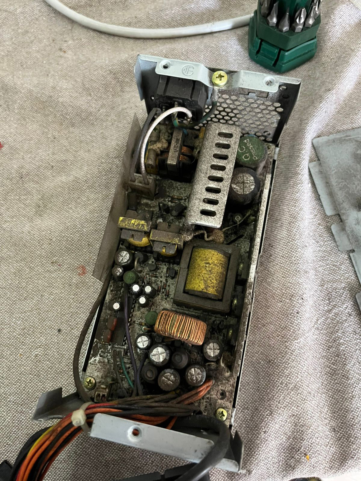
With the power supply completely dismantled, it was then easy to model it, but still copious measurements had to be taken...
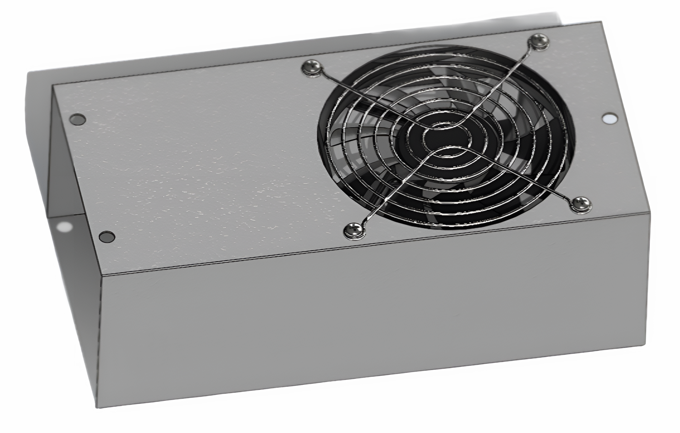
With the model for the power supply having been done, the rest of the work could begin...
Part Two - Design a nice gadget!
So with all the crucial parts 3D modeled, I could think about a design. That's when I noticed something at the day job.
In the rack behind my workspace sat these VMWARE boxes; apparently they are VeloCloud devices.
I kind of like their design so I did what great artists do,
shamelessly steal the design in my head and build on it!
I happened to find a card for those boxes so I scanned it as reference...

Since I would be doing the design around two major components I already had, there was absolutely no point in taking any measurements from the units at the day job at all!
Plastics Design Work
What I have been doing over the years has been to collect significantly well-designed consumer electronics enclosures.
This is a habit I formed during high school and one I still have to this day.
I learn by looking at what others are doing, and how things are designed- I do not have a degree on the wall and I found that it is pointless to have that (a discussion for another day).
For this particular design I knew it would be a two-part clip and screw system, so I looked at what I had for design ideas.
So in South Africa, we have this monopoly pay-tv service called DSTV. Over-over priced shit that is, and Netflix has made most people dump DSTV for streaming services.
So an awful lot of STBs (set top boxes) therefore make their way to me.
The plastics are of course well-designed by their contractors in Asia, and these units make good design studies.
This model of STB is no exception and this one was used to study two-part clip design.
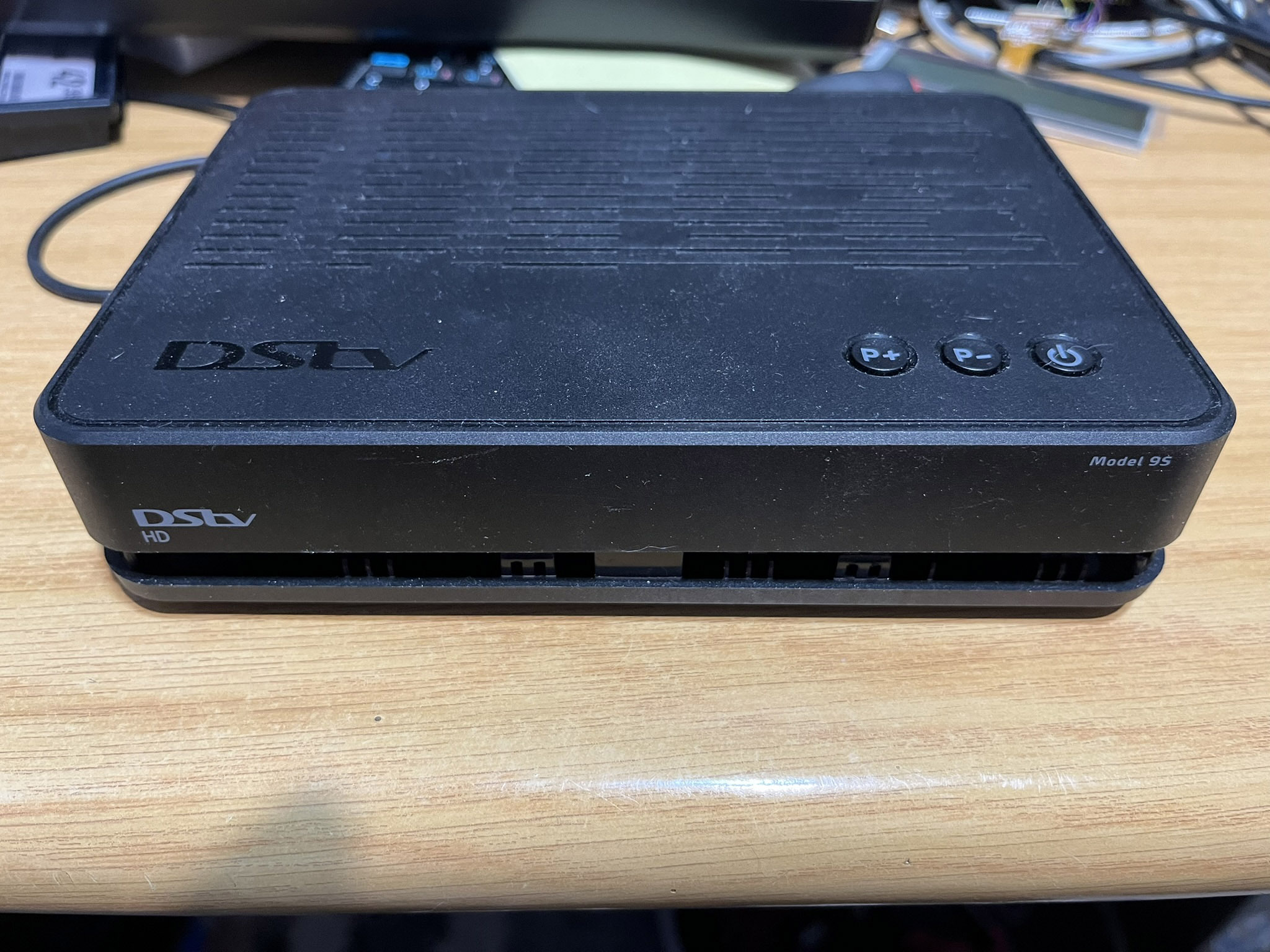
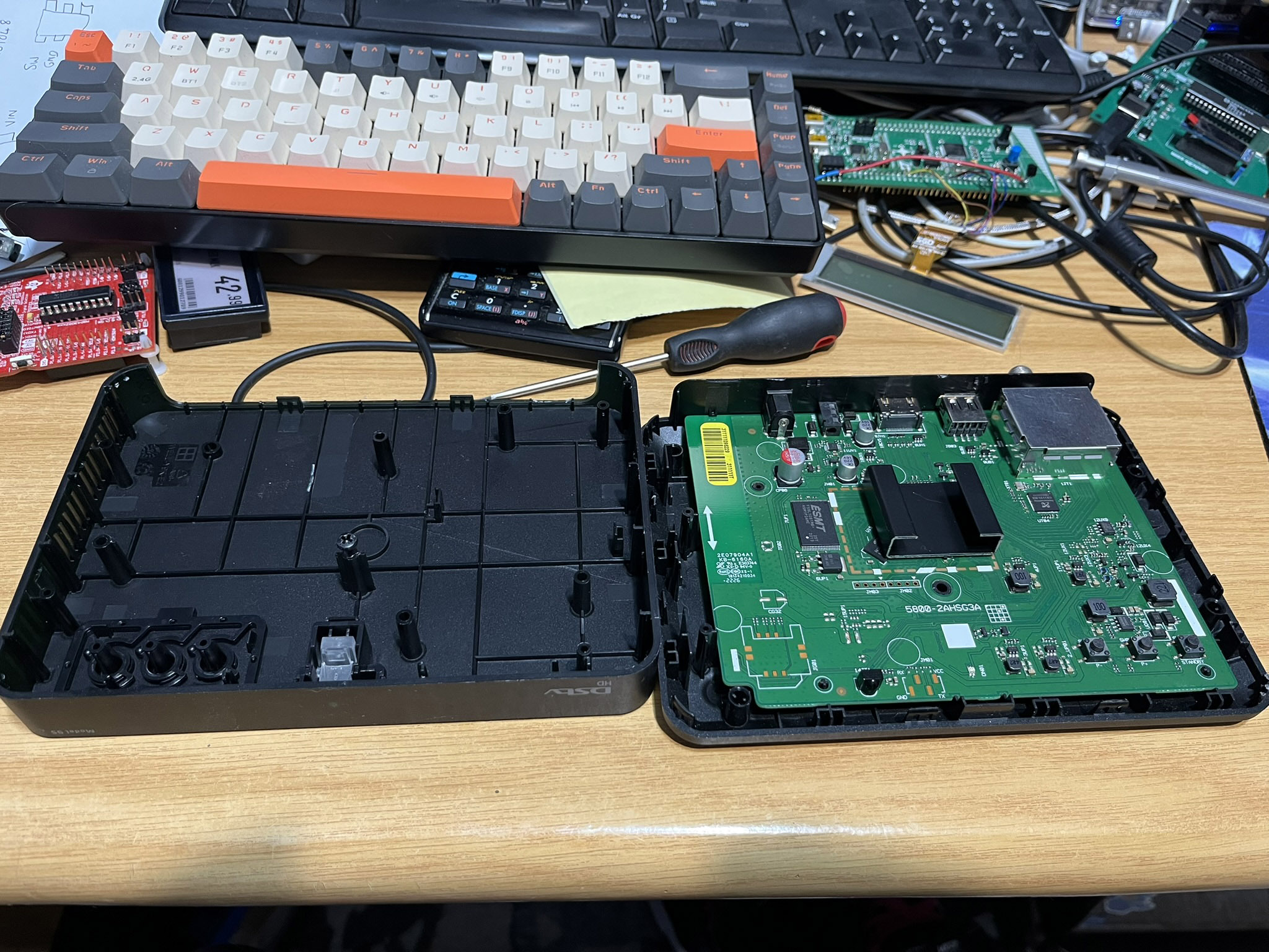
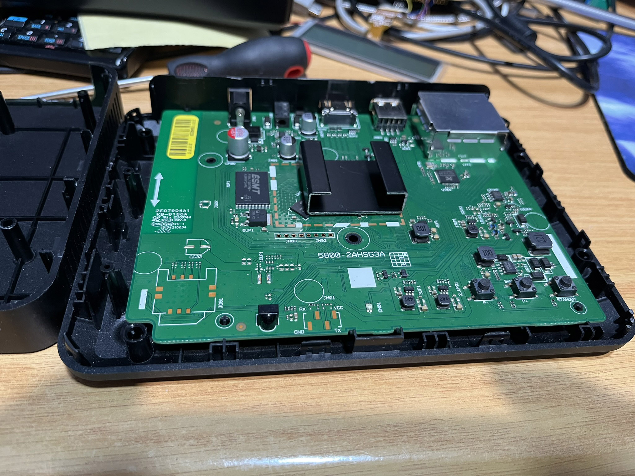
Below are detailed photos of the clip design
The photo below left shows the receiving part of the clip, the photo below right shows the bumps that lock into the clip
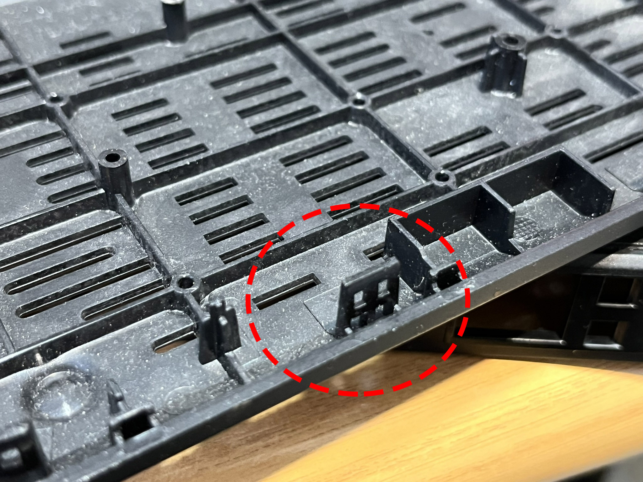
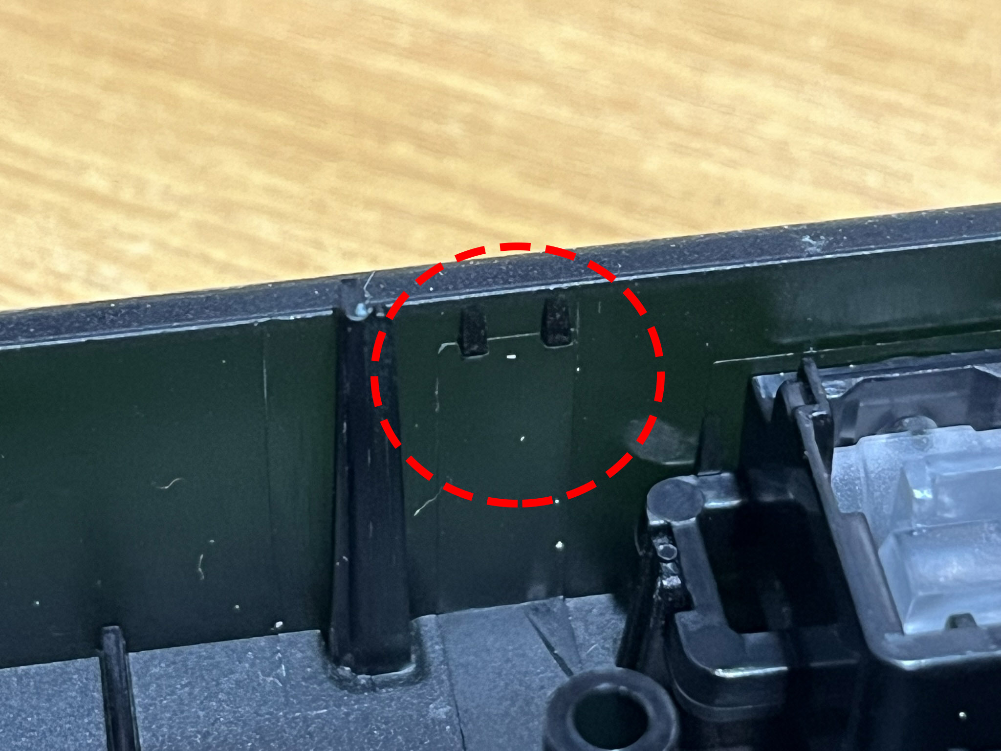
This clip design is very secure, evidenced by the amount of force I had to use to take that unit apart. So they'd be perfect for my application!
March 2026
I pushed hard and got the bottom part of the enclosure designed more or less. It was ready on the 15th of March
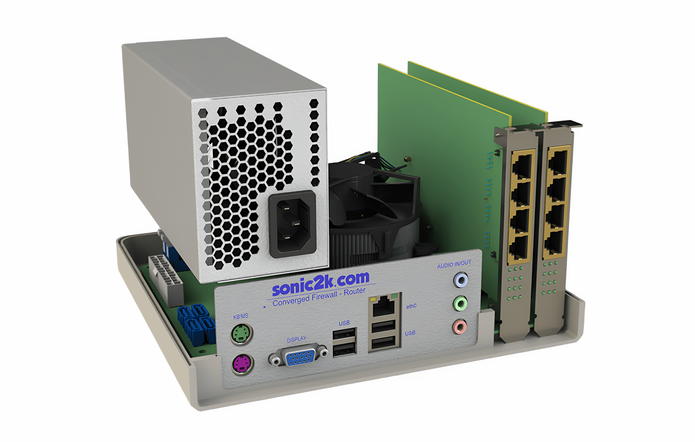
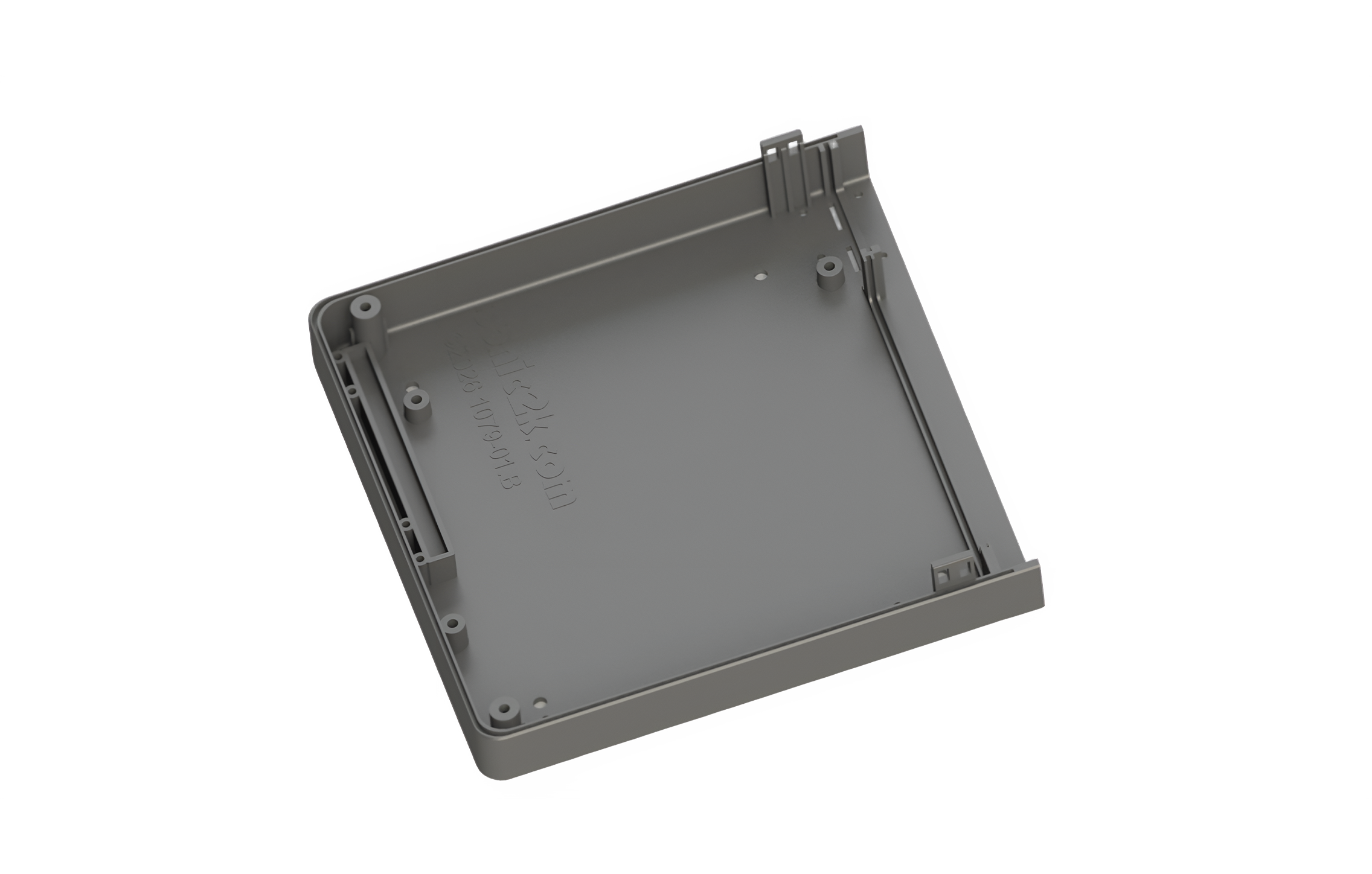
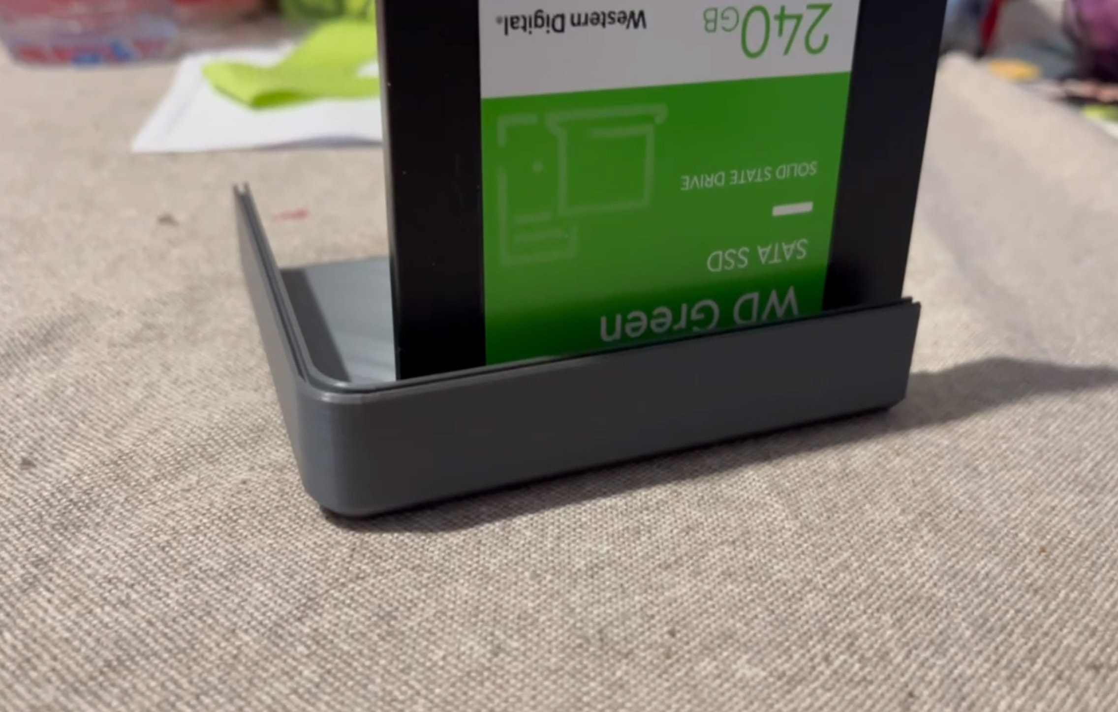
What I did before committing the bottom half design was do a test 3D print of the left bottom quadrant to ensure the pocket for the SSD was good, and it was!
Part 3 - Fabrication
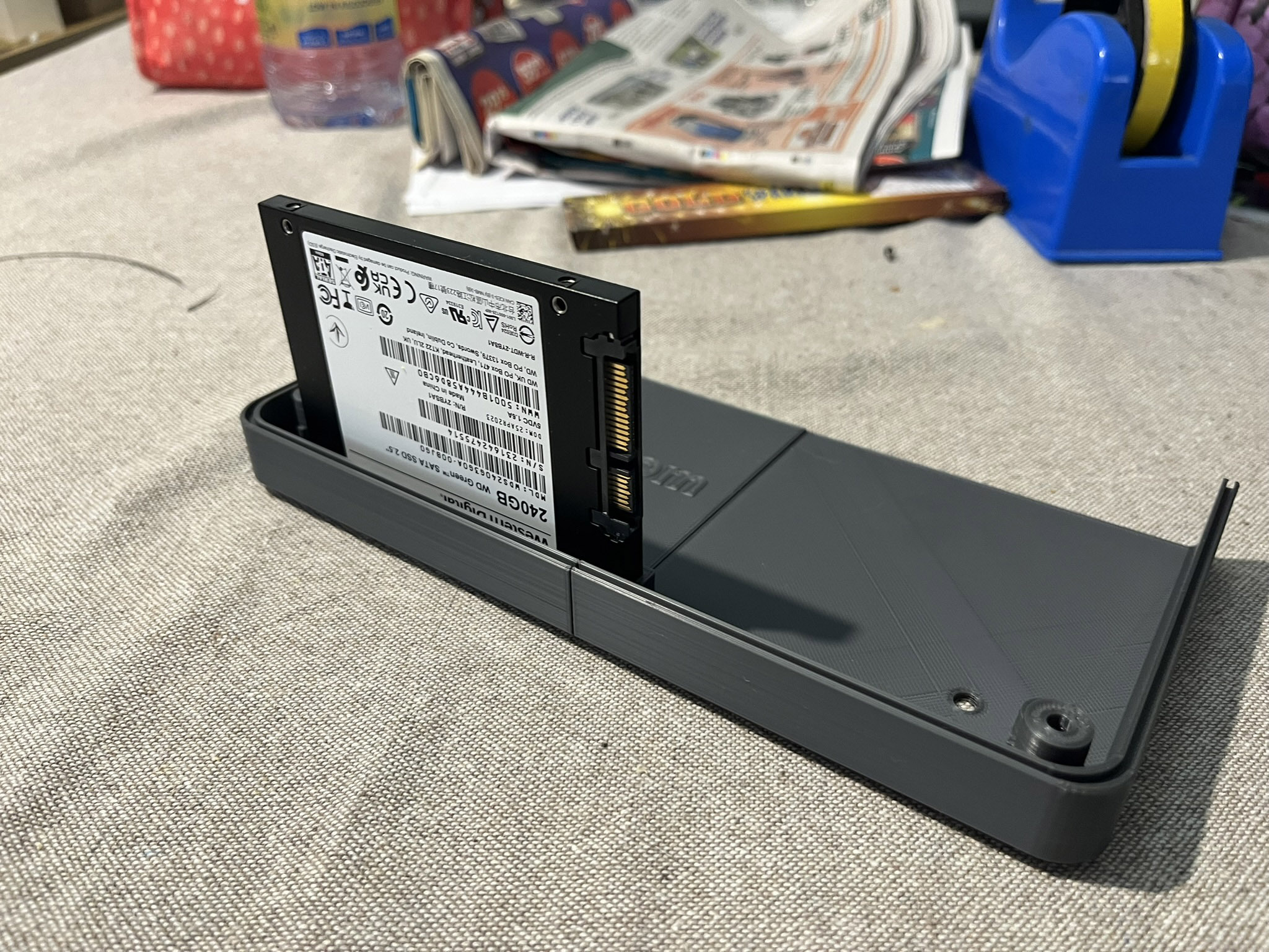
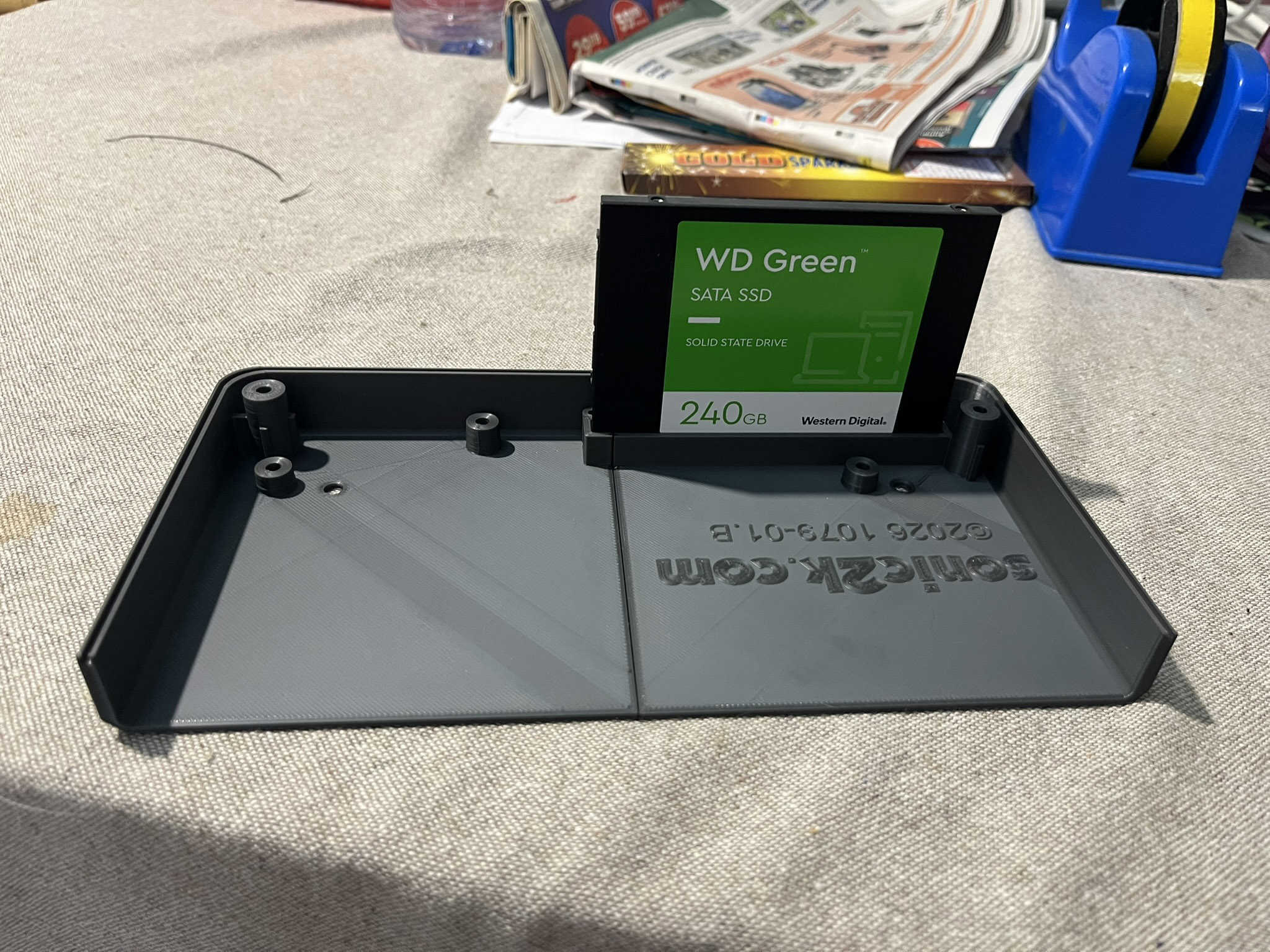
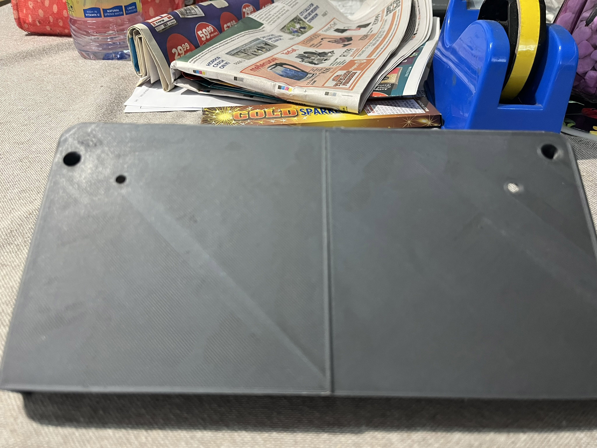
I began to print the bottom part of the enclosure. Because my Ender 3 V2 bed size is too small the whole model would not fit. The solution was to cut the model into quadrants,
print each quadrant independently, then glue them together...
(Credit: 3BT Tool and Die, Springs, Gauteng, RSA)
Lessons learnt so far
Cyanocrylate Adhesive (Crazy Glue) does NOT work well for this application. The bottom halves kept breaking apart. While the third and fourth quadrant were printing, I tackled other parts, a retainer for the SSD and a platform for the PSU to rest on.
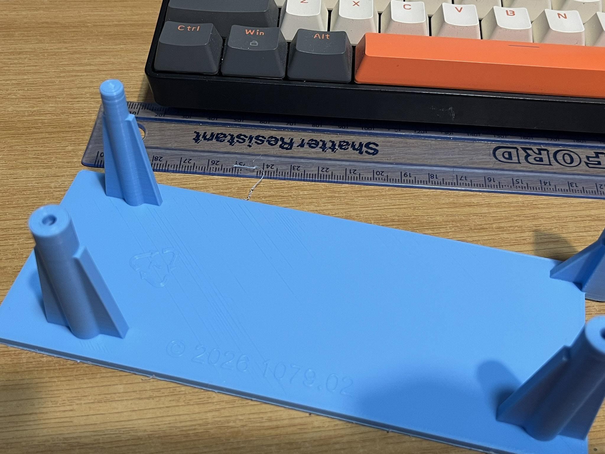
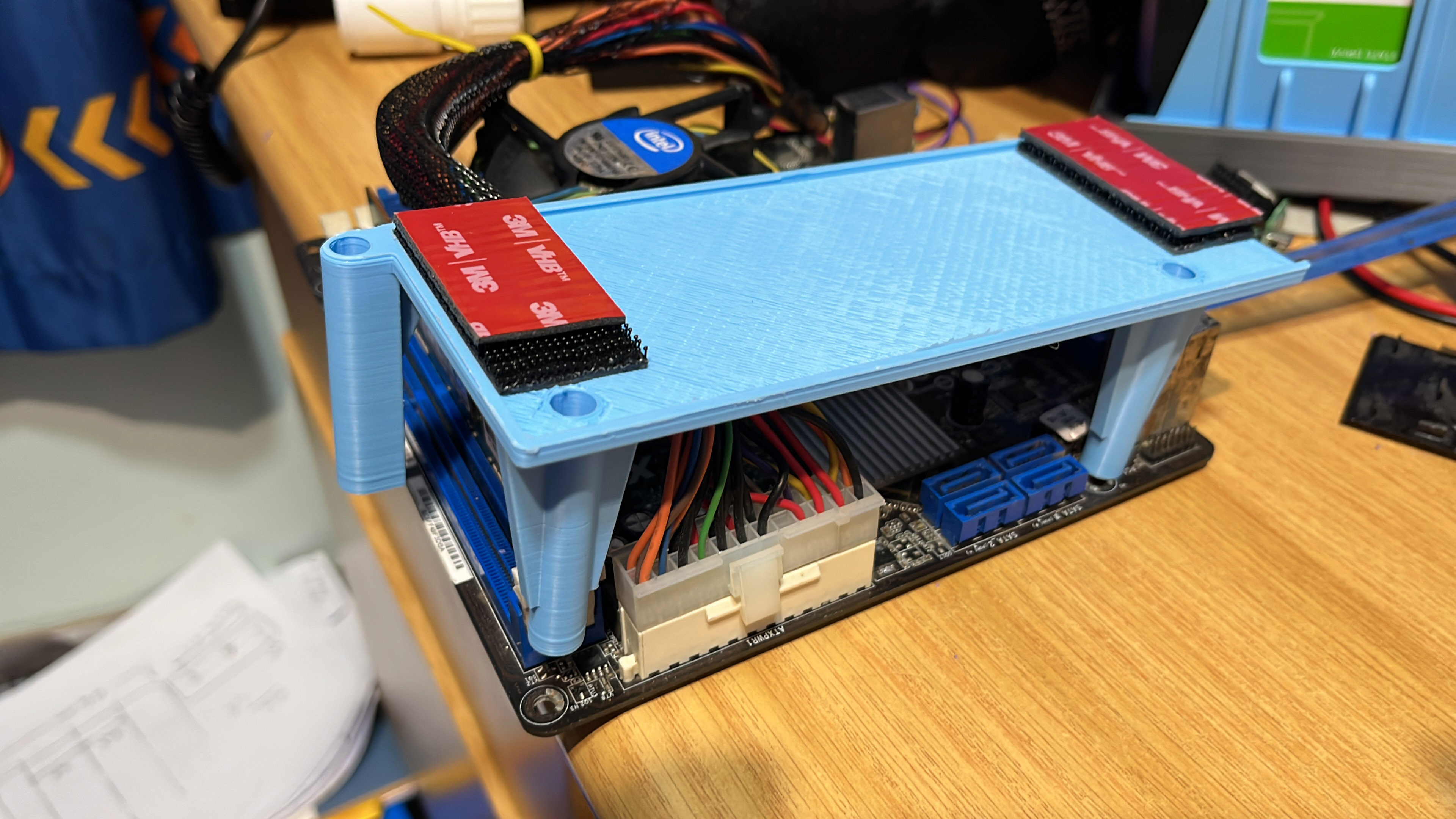
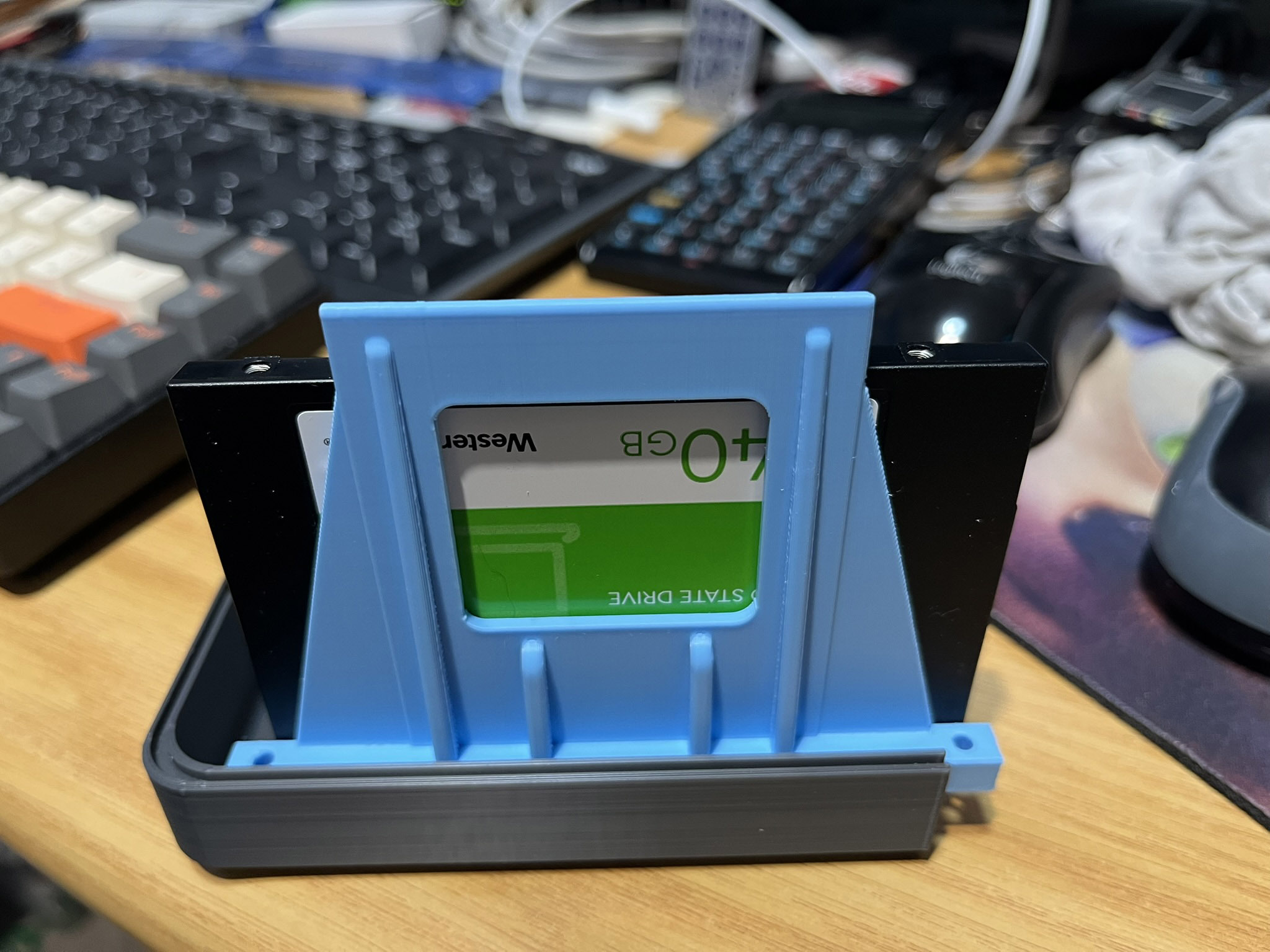
At this point it is obvious this machine has a model number. It's model 1079 of course!